3 Bit Asynchronous Up Counter Circuit Diagram. 3 bit binary up down ripple counter. The circuit diagram for the 3 bit synchronous down counter is the same as that of the up counter.
Asynchronous Counter from www.electronicshub.org
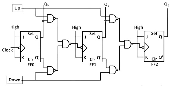
In the 3 bit ripple counter three flip flops are used in the circuit. In asynchronous counter a clock pulse drives ff0. All these flip flops are negative edge triggered but the outputs change asynchronously.
As this circuit is 4 bit up counter the output is sequence of binary values from 0 1 2 3 15 i e.
The clock pulse count is noted at the output of each flip flop q c q b q a where q a is the lsb and q c is the msb. As here n value is three the counter can count up to 2 3 8 values i e. The block diagram of 3 bit asynchronous binary up counter is shown in the following figure. Up down so a mode control input is essential.