Astable Multivibrator Using 555 Timer Lab Manual. By adjusting the time interval t of the charging or timing circuit the device can be made to work as a frequency divider circuit. Change c in simulator window and observe effect on output waveform frequency and dutycycle.
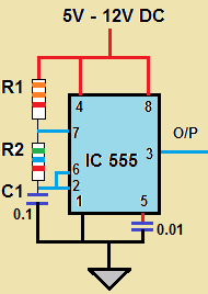
In astable mode capacitor c1 charges through resistors r1 and r2. When the voltage across c1 reaches 2 3 of the supply voltage c1 discharges through resistor r2 and the output goes low. In order to achieve pulse position modulation two 555 timer ic s are used in which one operates in astable mode and the other in monostable mode.
The output of this ic 555 is a pulse width modulated wave.
Change ra and rb in simulator window and observe effect on output waveform frequency and dutycycle. Monostable multivibrator using ic 555. Basic 555 astable multivibrator circuit. 5 wire the circuit schematic below which demonstrates how the 555 timer can function as an audio oscillator.
