Block Diagram 4 Bit Booth Multiplier Circuit Diagram. The block diagram of our proposed architecture of modified radix 4 booth algorithm is shown in figure 4. The 8 bit multiplicand and 8 bit multiplier are input signals into four booth encoders selectors.
When the two core parts of booth s multiplier design is done connect the block in a top level design as depicted in figure 1. Fsm prepared in experiment 6 can help you to implement booths fsm. The block diagram of our proposed architecture of modified radix 4 booth algorithm is shown in figure 4.
The 8 bit multiplicand and 8 bit multiplier are input signals into four booth encoders selectors.
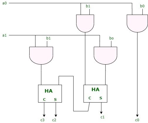
The following is the example of a 4 4 array multiplier. After applying booth s algorithm to the inputs simple addition is done to produce a final output. The block diagram of our proposed architecture of modified radix 4 booth algorithm is shown in figure 4. Radix 4 booth multiplier algorithm using combined p and.
