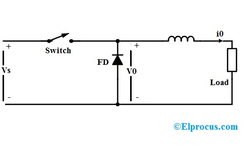
Class C Chopper Circuit Diagram. The principle of operation of chopper can be understood from the circuit diagram below. A chopper is a device that converts fixed dc input to a variable dc output voltage directly.
The circuit chops rectified dc output and varies the speed of dc motor. The chopper ch1 is switched off at point b and load current flows through path l load d1 l. When the value of l di dt is equal to back emf e b the load current becomes zero point c.
When the value of l di dt is equal to back emf e b the load current becomes zero point c.
The chopper ch1 is switched off at point b and load current flows through path l load d1 l. Carefully observe the circuit diagram. Type d chopper or two quadrant type b chopper two quadrant type b chopper or d chopper circuit. The diode d1 conducts during point b to point c.
