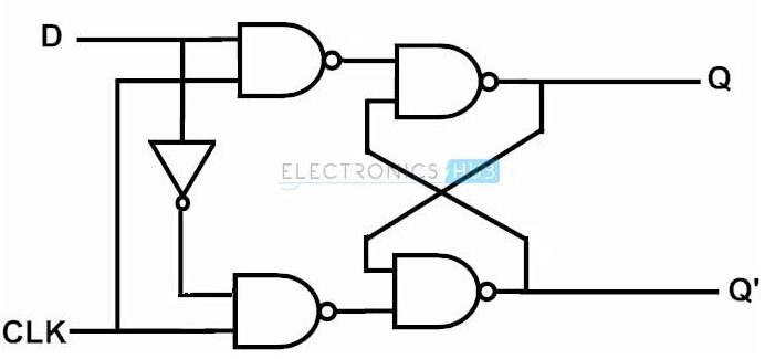
D Flip Flop Block Diagram And Truth Table. In order to complete the excitation table of a flip flop one needs to draw the q t and q t 1 for all possible cases e g 00 01 10 and 11 and then make the value of flip flop such that on giving this value one shall receive the input as q t 1 as desired. Thus d flip flop is a controlled bi stable latch where the clock signal is the control signal.
Since we are using the d flip flop the next step is to draw the truth table for the counter. Sr flip flops are used in control circuits. At other times the output q does not change.
So the display would start with displaying 1 2 3 and then 0.
Sr flip flop is the basic building block of d flip flop. Thus d flip flop is a controlled bi stable latch where the clock signal is the control signal. This block diagram consists of three d flip flops which are cascaded. Again this gets divided into positive edge triggered d flip flop and negative edge triggered d flip flop.
