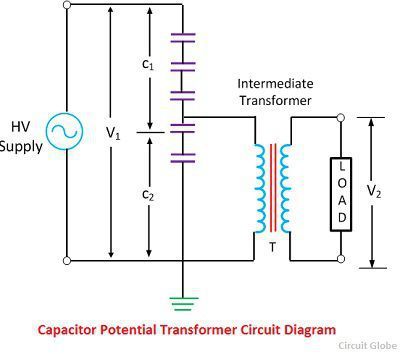
Equivalent Circuit Diagram Of Potential Transformer. Equivalent circuit when all the quantities are referred to secondary side. The circuit diagram of the capacitor potential transformer is shown in the figure below.
Equivalent circuit of transformer the equivalent circuit of transformer is shown in the figure. Calculation of various parameters of the transformer like resistance reactance impedance on the primary and secondary side can be done easily which in turn also used for determining the regulation efficiency and losses of the. Now let s dive into the topic and first of all let s get introduced to an actual transformer.
Basically an equivalent circuit is representing all the parameters of the transformer in a form of a circuit or diagrammatical manner.
Transformer equivalent circuit in phasor form in phasor form the transformer equivalent circuit takes the form shown in fig 3. The reactances are derived by multiplying the inductances by the radian frequencyω 2πf where f is the frequency. The stack of high voltage capacitor from the potential divider the capacitors of two sections become c 1 and c 2 and the z is the burden. Basically an equivalent circuit is representing all the parameters of the transformer in a form of a circuit or diagrammatical manner.
