Forward Biased Diode Connection Diagram. Keep in mind we are talking about a variable power source an ammeter in milli ampere range and a voltmeter. Answered oct 5 2018 by aayushgupta 77 5k points selected oct 6 2018 by faiz.
The pn junction for strengthening the potential barrier and prevents the flow of current through it is called reverse bias. When the positive side of the supply is connected to the p type and n type is connected to the negative side of the supply. In contrast to forward bias the reverse bias connection blocks the current passage and works as an open switch.
The above diagram shows the v i characteristics of the zener diode behavior.
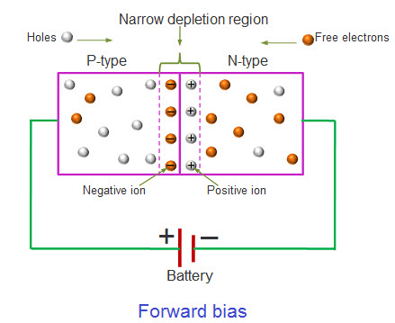
Reverse biased p. This bias condition is known as forward bias. Forward bias and reverse bias. Reverse biased p.
