Ideal Reheat Rankine Cycle Ts Diagram. Work done on pump per kg of water w p h 2 h 1. The result is an increase in q h and no change or even a decrease in q c.
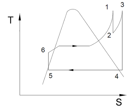
1 determine the pressure at which the steam should be reheated. The total heat input and total turbine work output for a reheat cycle become. The schematic of an ideal reheat rankine cycle is shown on the left with its t s diagram.
The result is an increase in q h and no change or even a decrease in q c.
Both of these effects result in a significant increase in the thermal efficiency. Steam leaves the boiler and enters the turbine at 4 mpa 400 circ c. Determine the cycle efficiency. Ideal rankine cycle a schematic representation of an ideal rankine cycle b t s diagram of an ideal rankine cycle.
