Lcr Series Resonance Circuit Experiment. Electrical properties of a series lcr resonant circuit fig. Module 9 set the groundwork for module 10.
The current i in a series lcr circuit is given by i e z e r 2 l ω 1 c ω 2. Module 9 set the groundwork for module 10. 1 77vlc in the circuit of fig.
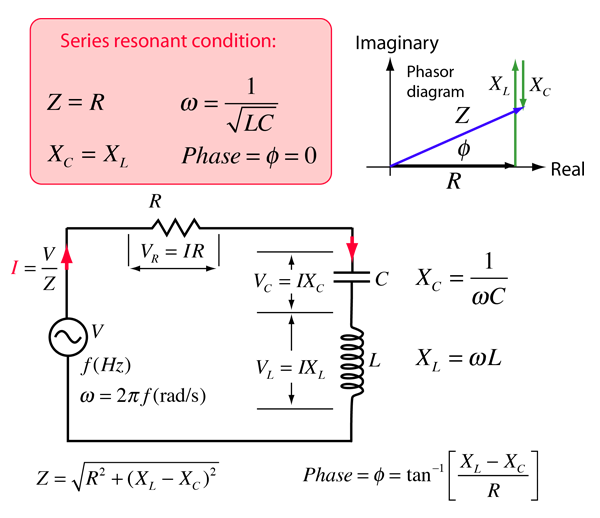
Electrical resonance is said to take place in a series lcr circuit when the circuit allows maximum current for a given frequency of the source of alternating supply for which capacitive reactance becomes equal to the inductive reactance.
27 1 xl and xc are equal at about 16 kilohertz as the formula shows. 9 2 1 fig 9 2 1a shows a series lcr circuit and fig 9 2 1b shows what happens to the reactances x c and x l resistance r and impedance z as the supply v s is varied in frequency from 0hz upwards. The formula for determining the resonant frequency of a series lcr circuit is. 1 to study the variation in current and voltage in a series lcr circuit.
