Locus Diagram Of Rl And Rc Circuit Experiment. For the purpose of understanding let us consider a simple circuit consisting of a capacitor and resistor in series with a power supply 5v. About press copyright contact us creators advertise developers terms privacy policy safety how youtube works test new features press copyright contact us creators.
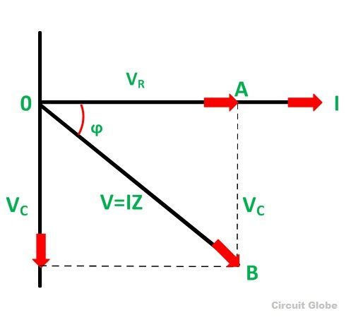
Basic principle of rc rl and rlc circuits. Ohm s law applies to all types of circuits but in the case of ac circuits all circuit quantities must be expressed as phasors. All calculations must be performed using phasor algebra.
All calculations must be performed using phasor algebra.
In this video phasor diagram representation of voltage and current for series rc rl and rlc circuit has been explained and the examples based on this phaso. Do the orcad simulations of both rc and rl circuits calculate time constants and plot the resulting waveforms across c in the case of rc and the waveform of the current in the case of rl. These instructions will use the notation τ rc for the time constant of either a. One thought on conclusion rlc circuits zerogoszinski may 15 2014 at 7 23 pm.
