Master Slave T Flip Flop Circuit Diagram. Figure 8 shows the schematic diagram of master sloave j k flip flop. Master slave flip flop.
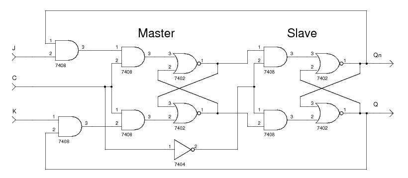
The slave ff can be is detached until the clk pulse goes to low which means to 0. Out of these one acts as the master and receives the external inputs and the other acts as a slave and takes its inputs directly from the master flip flop. Master slave j k flip flop is designed using two j k flipflops connected in cascade.
So the master flip flop output will be recognized by the slave flip flop only when the clk value becomes 0.
Master slave flip flop circuit master slave ff working. In other words if cp 0 for a master flip flop then cp 1 for a slave flip flop and if cp 1 for master flip flop then it becomes 0 for slave flip flop. The modern ic such as 74ls 74al 74als 74hc and 74hct don t have master slave flip flops in their series. Here the master flip flop is triggered by the external clock pulse train while the slave is activated at its inversion i e.
