Multiplier Circuit Truth Table. Multiplexer and demultiplexer the ultimate guide. Our second task was to create a logic diagram of a 4 bit binary adder subtractor which consisted of the chip that is a binary adder 7483 and four xor gates 7486 on the breadboard.
The truth table of a 4 to 1 multiplexer is shown below in which four input combinations 00 10 01 and 11 on the select lines respectively switches the inputs d0 d2 d1 and d3 to the output. This allowed me to verify the accuracy of my results and prove my truth table and breadboard circuit correct. Multiplexer and demultiplexer the ultimate guide.
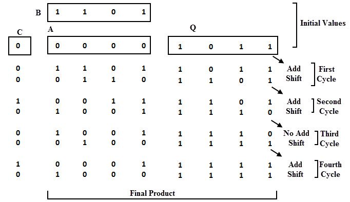
The product bit size will be the sum of the bit size of the input i e.
Our second task was to create a logic diagram of a 4 bit binary adder subtractor which consisted of the chip that is a binary adder 7483 and four xor gates 7486 on the breadboard. This allowed me to verify the accuracy of my results and prove my truth table and breadboard circuit correct. Code converters binary to excess 3 binary to gray and gray to binary. The product bit size will be the sum of the bit size of the input i e.
