Non Inverting Schmitt Trigger Output Waveform. Test data measurement points are given in table 8. The difference between the positive voltage vt and the negative voltage vt is defined as the input hysteresis voltage vh.
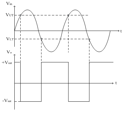
The output of schmitt trigger swings at upper and lower threshold voltages which are the reference voltages of the input waveform. The output of a schmitt trigger is a rectangular wave that drives an integrator. In electronics a schmitt trigger is a comparator circuit with hysteresis implemented by applying positive feedback to the noninverting input of a comparator or differential amplifier.
For a non inverting schmitt trigger circuit the input is simply connected to the non inverting input net on the op amp.
Measurement points table 9. In electronics a schmitt trigger is a comparator circuit with hysteresis implemented by applying positive feedback to the noninverting input of a comparator or differential amplifier. They are capable of transforming slowly changing input signals into sharply defined jitter free output signals. What will be the output waveform if the upper and lower threshold voltages are 0 25v.
