Non Inverting Schmitt Trigger With Reference Voltage. Since the output is high through the pullup resistor this creates a current path through the feedback resistor slightly increasing the reference voltage. This calculator first finds the exact resistor values to give the.
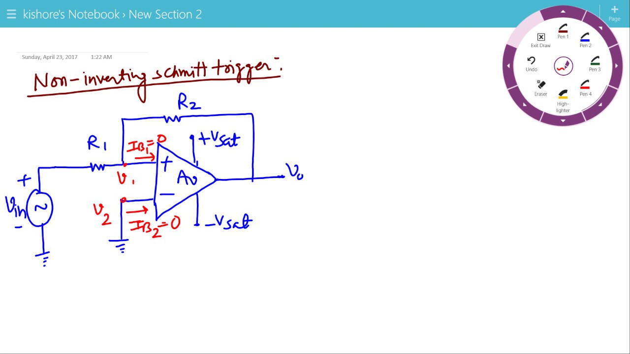
In this the voltage present at non inverting terminal v is compared with the voltage present at inverting terminal v 0v the operation of the circuit can be explained with the help of two conditions. The inputs switch at different points for positive and negative going signals. And positive feedback is applied from output to input.
When the input goes above the reference voltage the output goes low.
Since the output is high through the pullup resistor this creates a current path through the feedback resistor slightly increasing the reference voltage. In the non inverting configuration when the input is higher than a chosen threshold the output. The circuit diagram of the non inverting schmitt trigger is as shown below figure. In this the voltage present at non inverting terminal v is compared with the voltage present at inverting terminal v 0v the operation of the circuit can be explained with the help of two conditions.
