Positive Clamper Circuit Using Op Amp. Similarly a clamper circuit adds the negative dc component to the input signal to push it to the negative side. Positive and negative.
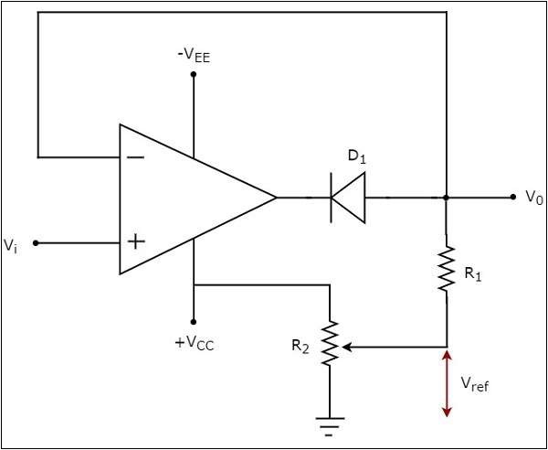
An op amp clamper circuit is one in which a predetermined dc level is added to the output voltage. If the clamped dc level is positive it is called positive clamper. The circuit diagramof positive clipper is shown in the following figure in the circuit shown above a sinusoidal voltage signal v t is applied to the non inverting terminal of the op amp.
Similarly a clamper circuit adds the negative dc component to the input signal to push it to the negative side.
A positive clamper is a clamper circuit that produces an output in such a way that the input signal gets shifted vertically by a positive dc value. Most of the electronic devices work on a single positive power supply except few like op amps oscillators etc. The circuit diagramof positive clipper is shown in the following figure in the circuit shown above a sinusoidal voltage signal v t is applied to the non inverting terminal of the op amp. If the circuit pushes the signal upwards then the circuit is said to be a positive clamper.
