Rfid Circuit Diagram Explanation. The chip obtains power from the rf signal transmit ted by the base station called the rfid reader. An rfid system consists of three parts.
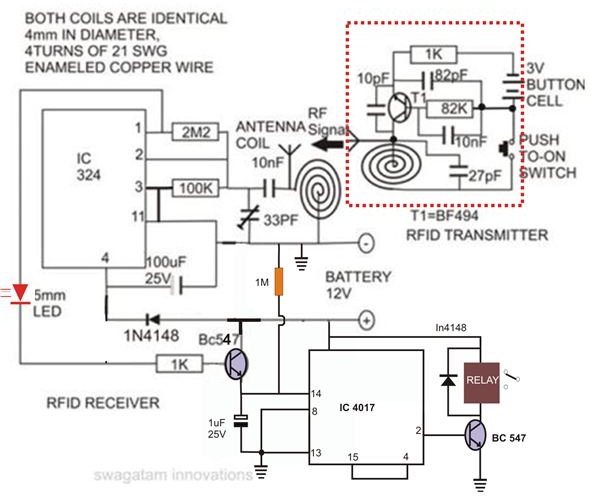
In this blog we ll be covering how rfid works and how you can create your very own rfid tag antenna circuit. The following explanation of the receiver circuit will give a clear picture of its internal functioning. In the present design of rfid for area security management the receiver circuit forms the lock and the transmitter forms the key.
Note that the above explanation is for a passive rfid tag.
As you can see the rf transmitter circuit consists of the encoder ic and rf receiver circuit consists of the decoder ic. And below ones showing the rf receiver circuit with breadboard setup. Since the transmitter does not need a regulated 5v we have directly powered it with a 9v battery. A typical rfid tag consists of an antenna and an integrated circuit chip both with complex impedances.
