Rl Series Circuit Waveform. When a square wave of voltage is applied to a series rl circuit results similar to those from rc circuits can be expected. The time constant of an rl circuit is the equivalent inductance divided by the thévenin resistance as viewed from the terminals of the equivalent inductor.
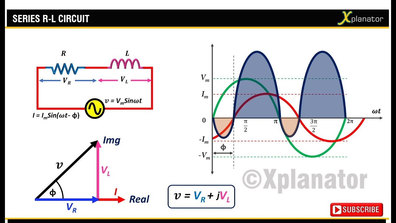
This lab is concerned with the characteristics of inductors and circuits consisting of a resistor and an inductor in series rlcircuits. The waveform and power curve of the rl series circuit is shown below. A resistor inductor circuit or rl filter or rl network is an electric circuit composed of resistors and inductors driven by a voltage or current source.
The expression for the current in the inductor is given by.
The primary focus will be on the response of an rl circuit to a step voltage and a voltage square wave. It consists of a resistor and an inductor either in series driven by a voltage source or in parallel driven by a current source. Note that the impedance triangle is geometrically similar to the circuit vector diagram and will have the same phase angle theta θ. The various points on the power curve are obtained by the product of voltage and current.
