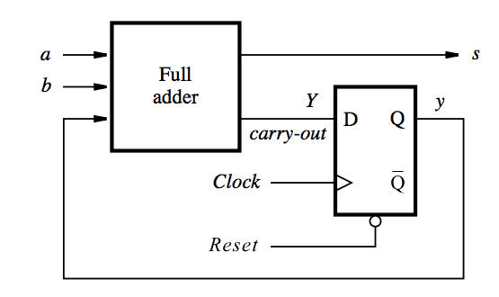
Serial Adder Diagram. In serial adders pairs of bits are added simultaneously during each clock cycle. To add the contents of two register serially bit by bit.
Let s0 and s1 are the states where the carry in values is 0 and 1 respectively. The output value sum depends on both state and the present value of the inputs a and b each transition is labeled using the notation ab sum which indicates the value of sum for a given values of a and b. State diagram for serial adder.
State diagram for serial adder.
For instance for a 4 bit adder four 1 bit full adders are needed. Block diagram for serial adder. The classic way to implement an n bit adder is to use n 1 bit full adders in parallel. Counter design using sequential circuits.
