Series Lcr Circuit Phasor Diagram. Figure 1 series lc circuit diagram lc series circuit characteristics. From physics alternating current class 12 haryana board english medium.
Ac Circuit Containing A Resistor An Inductor And A Capacitor In Series Series Rlc Circuit Phasor Diagram Circuit Diagram Formula Solved Example Problems Alternating Current Ac from www.brainkart.com
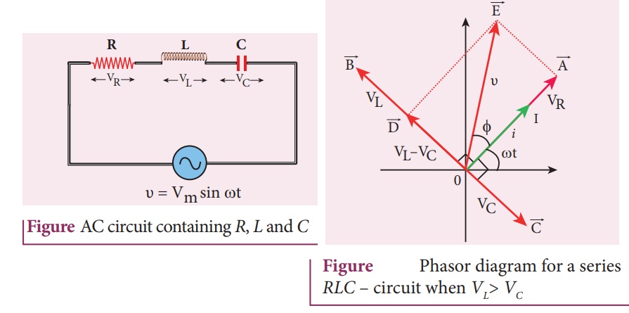
From the above phasor diagram we know that 1 now current will be equal in all the three as it is a series lcr circuit. A series lc circuit consists of an inductance and a capacitance connected in series as shown in figure 1. Figure 1 series lc circuit diagram lc series circuit characteristics.
Draw a plot showing the variation of the current i as a function of angular frequency ω of the applied ac source for the two cases of a series combination of i inductance l 1 capacitance c 1 and resistance r 1 and ii.
Draw a plot showing the variation of the current i as a function of angular frequency ω of the applied ac source for the two cases of a series combination of i inductance l 1 capacitance c 1 and resistance r 1 and ii. Since the current flowing through the circuit is common to all three circuit elements we can use this as the reference vector with the three voltage vectors drawn relative to this at their corresponding angles. Using the phasor diagram derive the expression for the impedance of the circuit. A series lc circuit consists of an inductance and a capacitance connected in series as shown in figure 1.