Sr Latch Diagram And Truth Table. There are also d latches jk flip flops and gated sr latches. So we will use this truth table to understand the sr latch as when one of the input is 1 the output of the nor gate will be 0.
While dealing with the characteristics table the clock is high for all cases i e clk 1. There is another type of latch which is set when s 0 low and this latch is known as active low sr latch. In the formal syntax we earlier gave a formal semantics for sentential logic.
Sr latch truth table march 29 2020 march 26 2020 by electricalvoice a latch is a basic memory element that operates with signal levels rather than signal transitions and stores 1 bit of data.
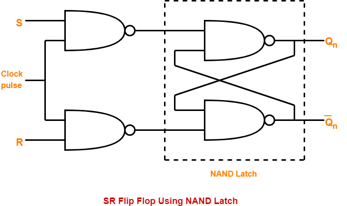
As the latch is set when s 1 high the latch is called active high sr latch. It can be constructed from a pair of cross coupled nor or nand logic gates. So the two inputs of nand gate b are 1 and q 1. Is the don t care condition.
