Sr Latch Timing Diagram Example. When the e 0 the outputs of the two and gates are forced to 0 regardless of the states of either s or r. Consequently the circuit behaves as though s and r were both 0 latching the q.
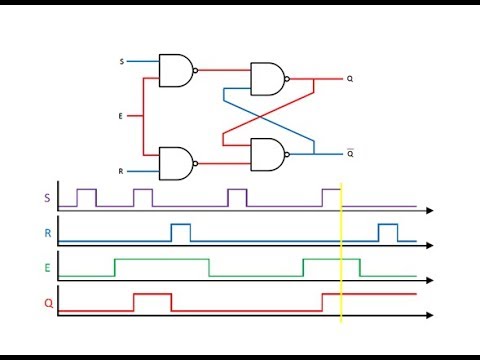
Working of sr nand latch. Sr latch q q 0 1 q q 1 0 q q 0 0 q q 1 1 sr 10 sr 01 sr 00 sr 10 sr 00 sr 11 sr 11 sr 01 sr 10 sr 01 sr 10 sr 11 possible oscillation between states 00 and 11 when sr 00 r s q q s r q 0 0 hold 0 1 0 1 0 1 1 1 disallow sr 00 sr 11 sr 00 10 observed sr latch behavior the 1 1 state is transitory either r or s gets ahead. Cse lecture the d latch.
The circuit can be made to change state by signals applied to one or more control inputs and will have one or two outputs.
T flip flops and sr latches. 2 sr latch using nand gate. Working of sr nand latch. Output depends on clock.
