Valve Timing Diagram Of 4 Stroke Engine Experiment. In a four stroke engine opening and closing of valves and fuel injection. Performance test and preparation of heat balance sheet on 4 stroke single cylinder diesel engine.
I C Engine Valve Timing from www.slideshare.net
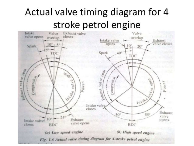
The valve timing diagrams of a marine diesel engine is a graphical representation of the exact moments in the sequence of operations at which the two valves i e. This is called the valve timing diagram. Valve timing diagram for 4 stroke engine petrol and diesel as we all know in 4 stroke engine the cycle completes in 4 strokes that are suction compression expansion and exhaust the relation between the valves inlet and outlet and piston movement from tdc to bdc is represented by the graph known as valve timing diagram.
Performance test on two stage reciprocating air compressor.
Inlet exhaust valves open and close as well as the firing of fuel in a 4 stroke marine diesel engine it is generally expressed in terms of angular positions of the crankshaft. Mechanical engineering ic engine lab actual vavlve timing diagram of 4 stroke diesel engine i v o inlet valve open 100 200 before tdc i v c inlet valve closes 250 400 after bdc f v o fuel valve open 100 200 before tdc f v c fuel valve closes 150 200 after tdc e v o exhaust valve open 390 500 before bdc. To draw the valve timing diagram of 4 stroke diesel engine. 4 stroke diesel engine tachometer frictional dynamometer stop watch weights and hangers sand fuel etc.